Sharing spectrum between radar and communications applications is
becoming more difficult due to the prevalence of wireless broadband
transmission and the consistent increase in users of the frequency
spectrum. Clever nondisruptive approaches will need to be innovative to
provide enough spectrum for these ever-growing applications, many of
which are governmental and safety-related.
A new and growing approach for sharing spectrum is dynamic spectrum
allocation, where frequency bands may be borrowed temporarily from
primary users if they are not using their systems. An example of this is
in the 5 GHz band, which is presently shared between radar and WiFi
communications. To use this spectrum where radar is the primary user,
the WiFi system must check for radar transmission before using the
frequency band. If a radar is detected in the band at any time during
use, the WiFi system must immediately vacate the spectrum.
Radar transmissions are important for many applications, such as
weather, air traffic control, homeland security, and defense. Because
radar bands are now being increasingly shared with communications,
particularly wireless 4G, radar designers and operators are concerned
about the availability of spectrum for their important functions.
Typically, radar transmission is bounded by a spectral mask, assigned by
governmental agencies such as the National Telecommunications and
Information Administration (NTIA) or Federal Communications Commission
(FCC) in the United States. In the new proposed approach, a spectral
mask will be determined based on (1) the location of surrounding communication users, (2) the frequencies of operation of the communication users, and (3)
the acceptable interference power levels at each communication receiver
at its operating frequency. This approach will allow radar transmission
to be optimized and to successfully perform its functions while
ensuring it does not interfere with communication users. Being able to
use this approach will enable a new paradigm for spectrum sharing that
will open spectrum to numerous additional users.
The scenario considered in our work pertains to adaptive radar transmitters. Cognitive radar is introduced by Haykin as a radar that can sense and respond to its environment [1], and Guerci discusses the concept of a knowledge-aided cognitive radar [2].
Haykin discusses the control of radar transmitter power level so that
the acceptable interference temperature of receivers is not exceeded [3], and discusses adapting the transmitted waveform based on a multi-objective trade-off [4].
However, much of the previous work describing the mechanics of
determining a transmit waveform based on other users has been in the
area of communications transmission, rather than radar. Our work focuses
on crafting radar transmission that is sensitive to nearby
communication handsets. Mahmoud discusses
spectrum shaping based on the presence of licensed users and a flexible
spectral mask, noting that orthogonal frequency division multiplexing
(OFDM) waveforms can provide spectral flexibility by either enabling or
disabling subcarrier sets [5]. Poston discusses how OFDM waveforms can be woven among existing licensed television channels [6], and Cabric discusses placing a mask on the transmit power of an OFDM signal to protect adjacent-band users [7].
Srinivasa discusses combining cognitive radio transmissions with
licensed user transmissions by placing a spectral mask on secondary user
signals so that interference from the secondary transmissions is below
the acceptable noise floor for primary signals [8]. The dynamic regulation of spectrum using market-based approaches is discussed by Delaere [9] and Xie [10].
The present paper describes the setup of how radar transmission
spectral masks can be adapted based upon wireless handset users in the
surrounding geographic region. This approach will allow circuit and waveform optimization algorithms developed by Fellows [11] and Eustice [12] to be applied based on surrounding spectrum users rather than on a traditional regulatory mask.
SECTION II
SPECTRUM SHARING APPROACH OVERVIEW
Consider a radar transmitter located near multiple communication
receivers. It is assumed that the radar transmitter is located at
coordinates (0,0), and communication receiver handsets are located at
positions that are known. Further, the maximum acceptable power density
that can be tolerated by the receivers at their operating frequencies
are assumed to be known to the transmitter. This information might be
known either through a wireless network in which the coordinates and
acceptable interference levels are communicated to the radar, or through
radar detection itself and estimated values of harmful interference
based on whatever knowledge of the receivers is available. We have
constructed a simulation setup in which receiver locations and
acceptable power density can be randomly generated using MATLAB.
The Friis transmission equation allows calculation of the power at a receiver  $(P_{r})$ based on the transmitted power
  $(P_{t})$, the distance from the transmitter to the receiver
  $(R)$, and the antenna gains of both the transmitter and receiver antennas
  $(G_{t},\ G_{r})$ [13]:
 TeX Source\begin{equation*}
P_{r}=\frac{G_{t}G_{r}\lambda^{2}}{(4\pi R)^{2}}P_{t}
\tag{1}
\end{equation*}
To simplify the problem, isotropic radiation is assumed for both the
transmitter and receiver antennas. In a real scenario, this is far from
accurate. However, it can be seen that these scenarios can be easily
placed into consideration using equation (1). For isotropic radiation,  $G_{t}=G_{r}=1$ in (1)
to allow simple solution, based only upon the distance between the
transmitter and receiver, the frequency of the receiver, and the
acceptable interference power at the receiver. Thus we can write (1) as
  TeX Source\begin{equation*}
P_{r}(f,R)=\left(\frac{c}{4\pi Rf}\right)^{2}P_{t}(f)
\tag{2}
\end{equation*} where we have set
  TeX Source\begin{equation*}
f=\frac{c}{\lambda}
\end{equation*} assuming free-space transmission. Assume there are
  $N$ handsets, the
  $n\text{th}$ of which has parameters
  $(R_{n},f_{n},p_{n})$ where
We will assume  TeX Source\begin{equation*}
f_{1}\leq f_{2}\leq f_{3}\leq\cdots
\end{equation*}
Then, from (2), if  $P_{r}(f_{n},R_{n})$ is the power received by the nth handset, then we require
  TeX Source\begin{align*} &P_{r}(f_{n},R_{n})=\left(\frac{c}{4\pi R_{n}f_{n}}\right)^{2}P_{t}(f_{n})\leq p_{n}\\
\text{or} &\qquad P_{t}(f_{n})\leq\left(\frac{4\pi R_{n}f_{n}}{c}\right)^{2}p_{n}
\tag{3}
\end{align*}
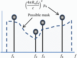
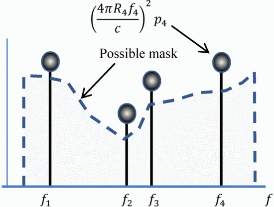
Figure 1 shows the construction of a mask for a
simple example using 4 handsets. In the case shown, the mask is placed a
certain specified level below the maximum acceptable power.
To solve in dB for the transmitted power, the logarithm of (3) is computed:
 TeX Source\begin{align*} &10\log_{10}[P_{t}(f_{n})]\leq 20\log_{10}\left(\frac{4\pi}{c}\right)+10\log_{10}p_{n}\\
&\qquad \qquad +20\log_{10}R_{n}+20\log_{10}f_{n}
\end{align*}
So in terms of dB  TeX Source\begin{equation*}
P_{t}^{dB}(f_{n})\leq C+p_{n}^{dB}+20\log_{10}R_{n}+20f_{n}^{Dec}
\end{equation*} where
  $f_{n}^{Dec}=\log_{10} \ f$ measures frequency in decades and
  $C=20\log_{10}\left(\frac{4\pi}{c}\right)$ is a constant.
SECTION III
SPECIAL CASES
1. Constant Range and Acceptable Handset Power
If  TeX Source\begin{equation*}
R_{n}p_{n}=\text{constant},
\end{equation*} then the allowable transmitted power
increases 20 dB per decade. This means that the allowable transmitted
power to avoid interference with a given handset with fixed position and
maximum acceptable interference power density (dBm/Hz) increases 20 dB
per decade. As a result, when radar transmit power is held constant,
interference is less likely at higher frequencies. However, for the same
reason, the radar transmitter must transmit with a power that is higher
by 20 dB per decade to illuminate a target at fixed distance, and with a
power that is higher by 40 dB per decade to achieve the same power in
the echo at the radar receiver. Thus, this tends to be a deceiving
scenario: for radar operation it may actually be better to operate at
lower frequencies in many cases.
2. Worst Case
Rather than fitting to each individual communication handset's
requirements, the mask can be piecewise fit to the worst case over given
intervals if desired. This provides a smoother mask which is, in most
cases, more restrictive on the radar transmission. Assume the parameters
can be constrained by intervals  TeX Source\begin{align*} &f_{-}\leq f_{n}\leq f_{+}.\\
&p_{-}\leq p_{n}\leq p_{+}\\
&R_{-}\leq R_{n}\leq R_{+}
\end{align*}
Then at that distance, (3) becomes  TeX Source\begin{equation*}
P_{t}(f_{n})\leq\left(\frac{4\pi f_{n}R_{n}}{c}\right)^{2}p_{n}\leq\left(\frac{4\pi f_{+}R_{+}}{c}\right)^{2}p_{+},
\end{equation*} where, for each parameter, we have chosen
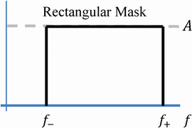
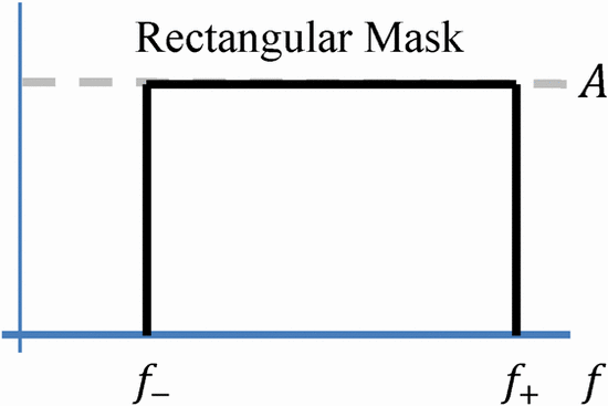
the upper limit of the allowable interval. This corresponds to a
rectangular mask with
  TeX Source\begin{equation*}
A=\left(\frac{4\pi f_{+}R_{+}}{c}\right)^{2}p_{+}.
\end{equation*}
Note the closer the handset is to the transmitter, the lower the mask amplitude. This rectangular mask is shown in Fig. 2.
3. Cell Specific
Equation (3) is satisfied when  TeX Source\begin{equation*}
P_{t}(f_{n})\leq\left(\frac{4\pi}{c}\right)^{2}\min_{n}R_{n}^{2}f_{n}^{2}p_{n}
\end{equation*} which gives us the rectangular mask with
  TeX Source\begin{equation*}
A=\left(\frac{4\pi}{c}\right)^{2}\min_{n}R_{n}^{2}f_{n}^{2}p_{n}
\end{equation*}
A single worst case handset determines the mask amplitude.
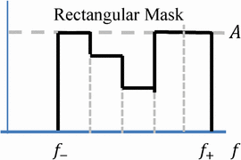
5. Piecewise Constant Approach
First, from (3), evaluate  TeX Source\begin{equation*}
P_{t}(f_{n})=\left(\frac{4\pi R_{n}f_{n}}{c}\right)^{2}p_{n}
\tag{4}
\end{equation*} for all
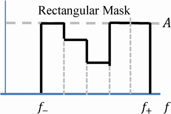
  $n$. Run a fixed length min sliding window over the series to get the mask. Figure 4 shows an example of this approach.
SECTION IV
SIMULATION RESULTS
A simulation setup has been created in MATLAB to allow the
development of this tool, which we plan to develop with increasing
complexity. Use of this developing tool is briefly demonstrated using
two simple scenarios. The frequency band from 3400 to 3700 MHz is used
for illustration purposes, as this is a band that is presently used (at
least in part) for spectrum sharing between radar and communications. In
fact, much of the S-band radar allocation has been re-allocated for
radar and communications sharing. The handset acceptable power density
(dBm/Hz), frequency, and location can either be either randomly
generated by the program or input on a spreadsheet to the program.
A. Simulation A
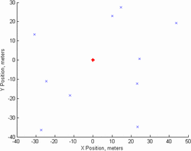
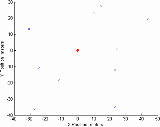
Figure 5 shows a simple scenario in which the
radar transmitter, notated in red, is located at the coordinates (0,0)
and handset receivers are located at the positions marked by ‘ $\text{X}$’
on the diagram. 10 handsets are used, all with frequencies between 3400
and 3700 MHz (this frequency range represents an actual frequency range
where radar and communications spectrum sharing is in use). The handset
settings are generated using the following inputs to the random
generator used in MATLAB:
-
Maximum receiver acceptable power density range: −75 to −65 dBm/Hz
-
Radar transmitter power density: 20 dBm/Hz
-
Frequency range: 3400 to 3700 MHz
-
X location: −50 to 50 meters
-
Y location: −50 to 50 meters
-
Number of devices: 10
Based on the frequencies and locations of the handset receivers, the
receiver acceptable power density, and the radar transmitter power
density needed for the radar application, the spectral mask can be
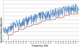
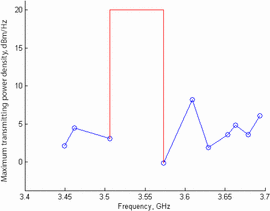
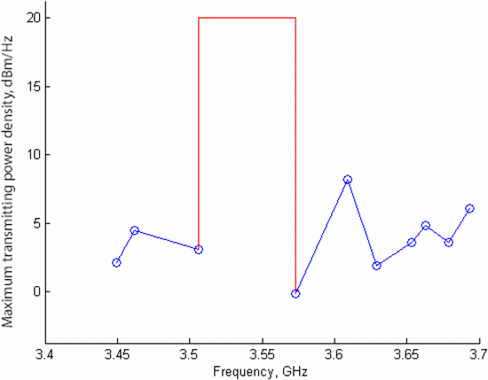
dynamically constructed. Figure 6 shows the spectral mask for the scenario in Fig. 5.
The algorithm chooses the main transmission band as 3.506 GHz to 3.573
GHz (bandwidth of 66.725 MHz), because this is the largest gap between
communication receiver handset frequencies. The main transmission band
part of the mask is indicated in red in Fig. 6. The remaining part of the mask, constructed based on handset data, is shown in blue.
The spectral mask is based on the power density of both the in-band
transmission of the radar and the maximum acceptable power density
transmitted at the frequencies of the handsets (traced to the
transmitter using equation (2)).
B. Simulation B
A second simulation was performed using the following settings. A
notable change in this simulation is the much larger number of devices:
1500 communication receiver handsets are used, all with operating
frequencies between 3400 and 3700 MHz.
-
Maximum receiver acceptable power density range: −85 to −65 dBm/Hz
-
Radar transmitter power density: 20 dBm/Hz
-
Frequency range: 3400 to 3700 MHz
-
X location: −50 to 50 meters
-
Y location: −50 to 50 meters
-
Number of devices: 1500
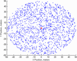
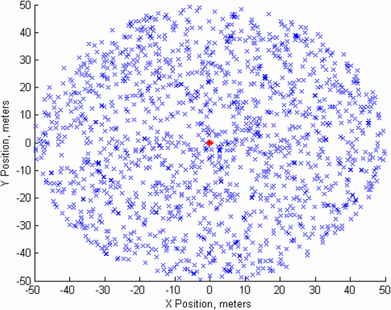
The locations of the communication handsets are shown in Fig. 7,
assuming that the radar transmitter, again notated in red, is located
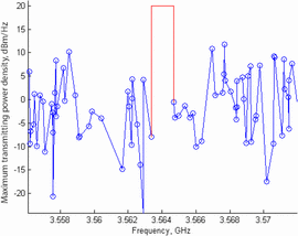
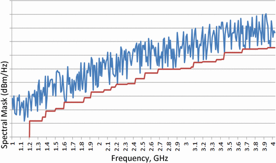
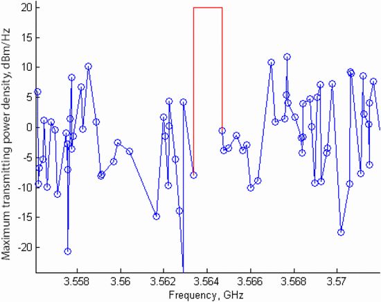
at the coordinates (0,0). This is a very busy environment. In Fig. 8,
the dynamic spectral mask is plotted by connecting the maximum transmit
power density at the handset frequencies to the in-band transmission
power. Again, the algorithm selects the widest frequency range available
in the pre-specified range to perform the transmission. Because of the
significantly higher number of devices, it can be seen that the
bandwidth for transmission is 1.312 MHz, significantly smaller than in
Simulation A. This will force the radar transmitter to adjust to fit a
tighter spectral mask. The difference between Simulations A and B
represents a scenario in which a radar transmitter must adapt from a
less crowded to more crowded wireless environment.
An initial simulation has been presented for the creation of a
dynamic spectral mask for radar transmission based on the locations and
maximum acceptable power density levels of surrounding communication
receiver handsets, which would ensure that a wireless communication
receiver does not become victimized by the radar transmission. This work
represents a first step toward a more complex platform in which the
spectral mask for radar transmission is based on its surroundings and on
system specifications. This platform can be expanded upon by
considering directivity of the radar transmitter and communication
receiver handsets, and other complicating factors such as atmospheric
attenuation and radar transmitter rotation.
Next steps to expanding this work include using the dynamic spectral mask to control load impedance [11] and waveform optimizations [12].
Putting this framework in place explores the upper-level scenario
control of the algorithms that will provide for reconfigurable radar
transmitters to optimize their circuitry and waveform to meet spectral
output requirements while achieving desired range/Doppler resolution
requirements (based on the ambiguity function) and power-added
efficiency.
Acknowledgment
This work has been funded by the National Science Foundation (Grant No. ECCS-1343316).


